6.4 The Multilayer_elliptic McXtrace Component
Elliptic multilayer mirror (in XZ)
Identification
-
Author: Jana Baltser, Peter Willendrup, Anette Vickery, Andrea Prodi, Erik Knudsen
-
Origin: NBI
-
Date: February 2011
Description
Reads reflectivity values from a data input file (Ref.dat) for a Si/W multilayer. The multilayer code reflects ray in an ideal geometry, does not include surface imperfections
The mirror is positioned such that the long axis of the mirror elliptical surface coincides with z-axis
The algorithm: Incoming photon’s coordinates and direction (k-vector) are transformed into an elliptical reference frame (elliptical parameters are calculated according to the mirror’s position and its focusing distances and the incident angle), the intersection point is then defined. A new, reflected photon is then starting at the point of intersection.
Example: Multilayer_elliptic( coating = ”Ref_W_B4C.txt”, theta = 1.2,
s1 = 1, s2 = 2, length = 0.1, width = 0.1, R0 = 1,
Emin=7, Emax=10, Estep=0.05)
Input parameters
Parameters in boldface are required; the others are optional.
|
Name |
Unit |
Description |
Default |
|
|
|||
|
coating |
str |
Datafile containing reflectivity values as a function of q and E. |
”Ref_W_B4C.txt” |
|
theta |
deg |
Design angle of incidence. |
1.2 |
|
s1 |
m |
Design distance from the source to the multilayer. |
0 |
|
s2 |
m |
Design focusing distance of the multilayer. |
0 |
|
length |
m |
alternate name for zdepth (obsolete) |
0.5 |
|
width |
m |
alternate name for xwidth (obsolete) |
0.2 |
|
R0 |
1 |
Maximal reflectivity |
1 |
|
Emin |
keV |
Lower limit of energy interval in datafile. Overrides what’s written in the datafile header. |
-1 |
|
Emax |
keV |
Upper limit of energy interval in datafile. Overrides what’s written in the datafile header. |
-1 |
|
Estep |
keV |
Step between energy sample points in datafile. Overrides what’s written in the datafile header. |
-1 |
|
Gamma |
|
High electron density fraction of bilayer (in kinematical appr.). |
0 |
|
Lambda |
m |
Thickness of bilayer (in kinematical appr.). |
0 |
|
rho_AB |
|
Number electron density constrast in bilayer (in kinematical appr.). |
0 |
|
N |
1 |
Number of bilayers (in kinematical appr.). |
0 |
|
xwidth |
m |
Width of the mirror along X-axis. |
0 |
|
zdepth |
m |
Length of the mirror along Z. |
0 |
|
|
|||
|
|
|||
|
|
|||
Links
-
Component source code found in file Multilayer_elliptic.comp.
Elliptically curved mirror coated with a multilayer
The component Multilayer_elliptic models a single rectangular reflecting multilayer mirror plate with elliptical curvature. It can be used as a sample component, to e.g. assemble a Kirkpatrick-Baez focusing system or in combination with a double-crystal monochromator.
Figure 6.1Left shows a side view of a mirror (the blue section of the ellipse) in the McXtrace coordinate system. At the mirror center, the mirror tangent is parallel to the \(z\) axis and the mirror normal is parallel to the \(y\) axis. The width of the mirror is \(w\) and in \(y-z\) plane the mirror has the curvature of an ellipse with major axis \(a\) and minor axis \(b\), \begin {equation} \frac {z^2}{ a^2} + \frac {y^2}{b^2} =1\,, \,|x| < \frac {w}{2}\,. \end {equation} The length of the mirror is \(L\). The coordinates of the mirror center \((0,Y_0,Z_0)\) and the ellipse parameters \(a\), \(b\) are determined uniquely by the central glancing angle, the source-mirror distance and the mirror-image distance. The position of the mirror is chosen to be at the positive side of the \(y\) axis.
The input parameters of this component are: theta [\(^{\circ }\)], the incident angle; s1 [m], the distance from the source to the multilayer; s2 [m], the focusing distance of the multilayer; length [m], the length of the mirrors; width [m], the width of the mirror along the \(x\)-axis; R, the reflectivity.
6.4.1 Definition of the reference frames
The direction and position of the incoming photon is defined relative to the coordinate system illustrated in Fig. 6.1Left (in the code referred to as McXtrace coordinate system):
-
the y-axis is parallel to the central mirror normal
-
the z-axis is parallel to the central mirror tangent
-
the origin is at the mirror center
However, all the calculations are conducted in another reference frame which is illustrated in Fig. 6.1 Right(in the following referred to as the Ellipse coordinate system):
-
the z-axis is parallel to major axis of ellipse
-
the y-axis is parallel to minor axis of ellipse
-
the origin is at the center of the ellipse
-
the mirror center at \((0,Y_0,Z_0)\), uniquely determined by the glancing angle at the mirror center, the source-mirror distance and mirror-image distance.
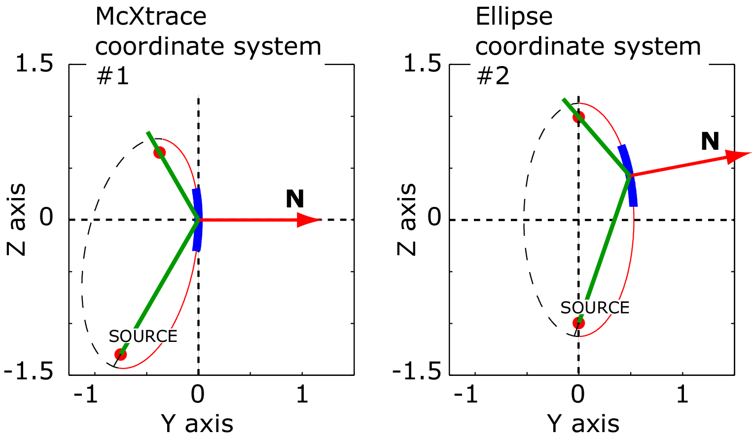
| Figure 6.1.: | The same image in different coordinate systems. Left: McXtrace System with the y-axis is parallel to the central mirror normal, the z-axis is parallel to the central mirror tangent and the origin is at the mirror center. Right: Ellipse System with the z-axis parallel to major axis of ellipse, the y-axis is parallel to minor axis of ellipse and the origin is at the center of the ellipse. |
6.4.2 Algorithm
-
The photon is generated with a starting point \(\mathbf {S}\) and a direction \(\mathbf {V}_\textrm {in}\) defined in the McXtrace coordinate system.
-
All calculations are performed in the Ellipse coordinate system, so to proceed the basis is changed to that reference frame.
-
The 2 intersections of the ray with the ellipse are determined.
-
It is checked if any of the intersections are within the area defined by the mirror.
-
If one of the solutions is valid, the reflection of that ray is determined.
-
The coordinates of the starting point and direction of the reflected ray are calculated using the basis of the McXtrace coordinate system.
6.4.3 Reflection of the ray in the mirror
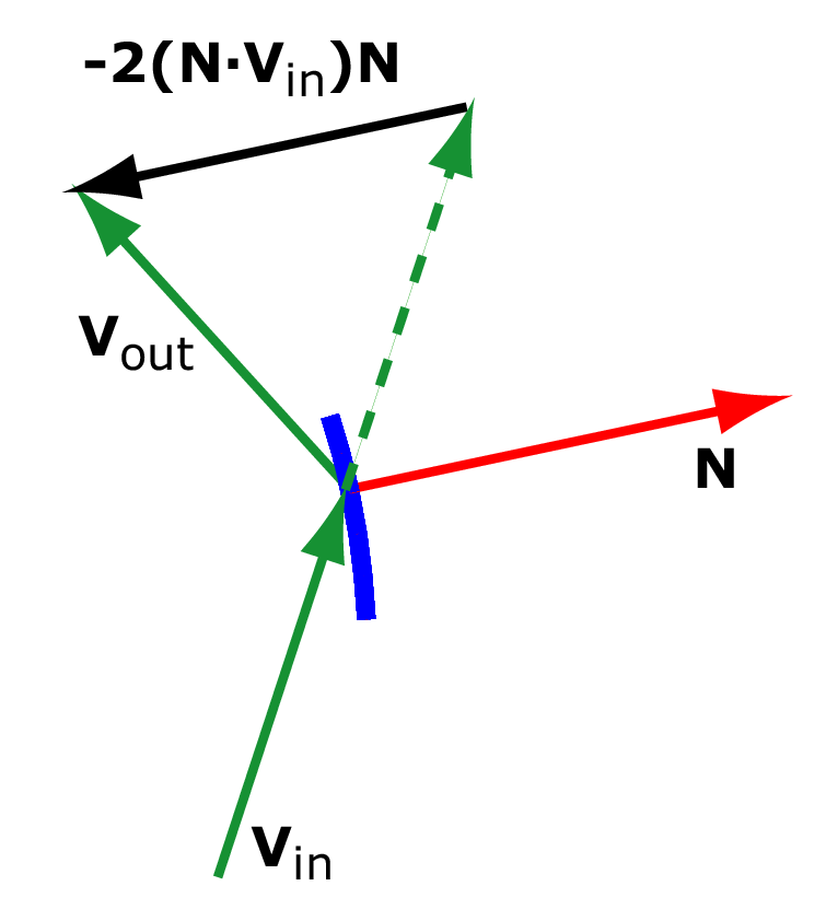
| Figure 6.2.: | The reflection of the unit vector \(\mathbf {V}_\textrm {in}\) in the mirror with the normal unit vector \(\boldsymbol {{N}}\) is \(\boldsymbol {{V}}_\textrm {out} = \boldsymbol {{V}}_\textrm {in} -2(\boldsymbol {{N}}\cdot \boldsymbol {{V}}_\textrm {in})\boldsymbol {{N}}\) |
The tangent and normal to the ellipse \(z^2/a^2 + y^2/b^2=1\) at the point \((Y,Z)\) are found by implicit differentiation: \begin {equation} \frac {2z}{a^2} + \frac {2y}{b^2} \,\frac {dy}{dz} = 0\,, \end {equation} so at the point \((Y,Z)\) the slope of the tangent is \(\frac {dy}{dz} = -\frac {Z\,b^2}{Y\,a^2}\). The slope of the normal is minus the inverse of the tangent slope, so the coordinates of the mirror normal are \begin {equation} N_x = 0 \quad N_y = \frac {a^2\,Y}{b^2\,Z} \quad N_z = 1\,. \end {equation} With \(\mathbf {V}_\textrm {in}\) and \(\mathbf {N}\) denoting unit vectors (direction and normal respectively), the direction of the reflected ray is calculated as \begin {equation} \boldsymbol {{V}}_\textrm {out} = \boldsymbol {{V}}_\textrm {in} -2(\boldsymbol {{N}}\cdot \boldsymbol {{V}}_\textrm {in})\boldsymbol {{N}} = \left ( \begin {array}{c} V_{\textrm {in}x} - 2(\boldsymbol {{N}}\cdot \boldsymbol {{V}}_\textrm {in})N_x \\ V_{\textrm {in}y} - 2(\boldsymbol {{N}}\cdot \boldsymbol {{V}}_\textrm {in})N_y \\ V_{\textrm {in}z} - 2(\boldsymbol {{N}}\cdot \boldsymbol {{V}}_\textrm {in})N_z \\ \end {array} \right ) \end {equation}
6.4.4 Mirror reflectivity
At present, the Multilayer_elliptic Mirror component uses a reflectivity table reflect, which 1st column is q [\(\AA ^{-1}\)] and from the 2nd column on as the reflectivity \(R\) in [0-1] as function of tabulated energy [\(\mathrm {keV}\)]. An example file, calculated for a particular \(Si/W\) multilayer, is provided (reflectivity.txt). User provided reflectivity data files can be parsed by the component.